
Design by tmartin · Original design · CC-BY-4.0 · Source details. Indexed via 3DCarParts. Source text and images remain credited to their creators; no modified design files supplied.
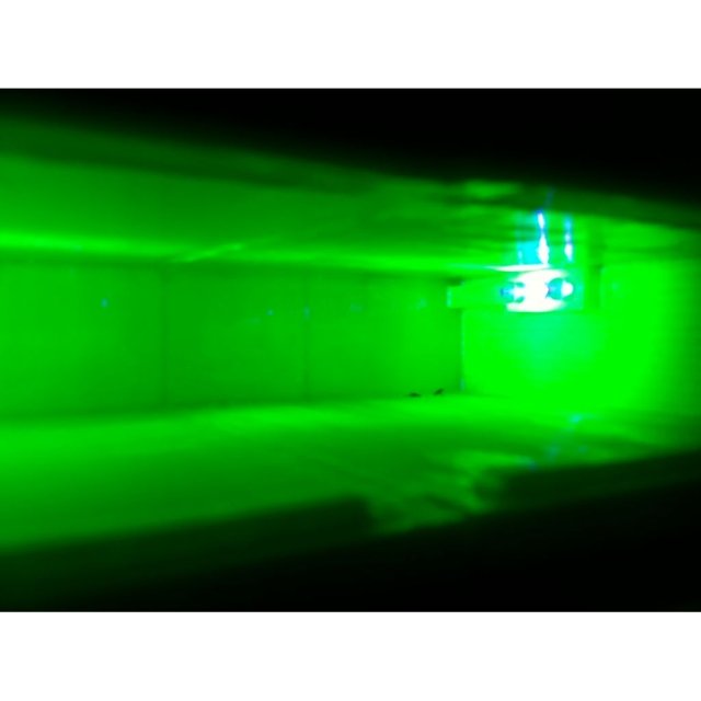
Designer source image. It may show an installed part, prototype or render; it is not an Orphaned Parts production sample.
2DIN to 1DIN Stereo Mounting Adapter
2DIN to 1DIN Stereo Mounting Adapter design listed for 1996 Ford Explorer. Listed category: interior. Verify dimensions, fitment and material suitability before printing.
- Make
- Ford
- Model
- Explorer
- Year range
- 1996
- Submodel
- Not supplied
- Engine
- Not supplied
Source approval status: pending. Source flags do not certify fit, material suitability or safety for your vehicle.
License conditions, files, application and fit are reviewed before work is accepted.
Description
Features:
The adapter has a large opening in the front to allow you to store CDs, remotes, papers, etc. There is a little lip on the front to prevent stuff from sliding out when you accelerate. The coolest feature is the three 5mm holes and channel on each side. These are intended for you to insert 3 LEDs and run the wiring through the channel so as to create a neat lighting effect. I found the coolest effect to be from producing the plastic parts entirely in Nuclear Green ABS: http://store.makerbot.com/nuclear-green-abs-1kg-spool-3mm-filament.html
The LEDs were UV: http://www.radioshack.com/product/index.jsp?productId=3107633
This creates an effect where the lighting comes almost entirely from the fluorescence of the plastic and is thus much more diffuse and less likely to glare into your eye while driving at night. It's also just very unique looking.
Note: In the third image from bottom the apparent double image of the 3 LEDs is caused by reflection off the top plastic surface, showing how shiny it is after treatment with acetone.
The bottom image is how the radio/lighting setup would appear from the vantage point of the driver looking down at night.
The top image of course looks straight in and is far brighter than the driver would see. Still it is important for safety reasons to wire it to an external switch rather than just wiring it to the ignition or the instrument light control so that it can be switched off manually if it becomes too bright or distracting.
Source description, under the recorded CC-BY-4.0 license.
Print instructions
Attach the parts together in the manner shown by the "assembled" file. Most types of glue should work, however I strongly recommend using ABS (of the same color) dissolved in acetone. I also recommend lightly brushing the interior with this paste to cover up any seams, as well as applying a thickish coating to the outside of the part for strength (you won't see that part anyway)
Once the parts are assembled, acquire your LEDs of the chosen color and wire them up so that they can run on car voltage (12V w/engine off, up to 14.5V with engine on). The wiring you choose will depend on the type of LEDs you use. In my case I used UV leds with a voltage rating listed as being from 3.3-4.0V. I wired each side of three in series and the two sides in parallel with eachother. The desired forward current is 20mA, so I used a series resistance in each strand of 168Ω as follows:
voltage drop of 3.7V*3LED (series) = 11.1V
14.5-11.1=3.4V Volts that we need to drop to protect the LED
Forward current in LED=20mA
so R=3.4V/0.02A=170Ω
I had 100Ω and 68Ω resistors available at my local radio shack, so each series string of LEDs consisted of 1*100Ω resistor, 1*68Ω resistor, and 3*UV LED. Two of these strings are run in parallel off of the supply to the car battery and a switch breaking both circuits wired to the outside and mounted under the dash. I recommend wiring the resistors some distance from the LEDs so that you only have to run two wires through the little channel that leads to the back. Be sure to use lots of electrical tape and/or heat-shrink tubing to insulate all the wiring to prevent any risk of shorting and fires. The total current draw is 0.04A with the engine running, less when running off battery. That means it uses only 0.48W of power and can be left on for quite awhile if desired.
Once the lighting and wiring is succesfully attached and tested, place the radio on top of the plastic piece and slide both into the radio slot of the car where they should lock in place/hold in place with friction. The cross-braced portion faces up, and the opening out. Some radios have screw holes for attachment purposes and it may be advisable to design small adapters to allow these to screw to the plastic unit.
Settings from the source; not independently tested by Orphaned Parts.
Print price estimates
Planning prices for one print, not a final quote. Defaults use a size allowance inferred from the part name, not a measured or sliced model. Filament suitability must be confirmed.
| Filament | USD / print | Application notes |
|---|---|---|
| PLA | $28.50 | Indoor prototypes; not a default material for hot vehicle interiors. |
| PETG | $29.00 | General-purpose candidate; heat and creep need review. |
| ASA | $32.50 | Candidate for UV exposure; verify temperature and geometry. |
| ABS | $31.50 | Enclosed printing; review application and dimensions. |
| TPU | $37.50 | Flexible designs only; not a substitute for rigid materials. |
| Nylon | $37.50 | Moisture, tolerances and application require review. |
| PA-CF | $42.50 | Filled nylon; abrasive filament and fit need review. |
Pricing assumptions and exclusions
USD: ($6 setup + $3 finishing + filament weight × assumed spool cost × 1.25 waste allowance + print hours × $2.50 × material time factor) ÷ 0.65. Rounded up to the next $0.50.
Assumed spool costs per kg: PLA $25, PETG $30, ASA $40, ABS $30, TPU $45, Nylon $65, PA-CF $95. Time factors: PLA/PETG 1.0, ASA/ABS 1.2, TPU 1.6, Nylon 1.4, PA-CF 1.5. These are proposed shop rates, not measured production costs.
Design work, test fitting, hardware, shipping and tax are additional where needed. Multi-file sets may need several prints. Use actual sliced weight and time when available. Final pricing is confirmed in writing.
All available source data
- Id
- 4ebd6a5b-aa8e-4291-b529-291ba3c85100
- Part Name
- 2DIN to 1DIN Stereo Mounting Adapter
- Slug
- 2din-to-1din-stereo-mounting-adapter
- Category
- interior
- Cswp Approval Status
- pending
- Download Status
- approved
- Make
- Ford
- Model
- Explorer
- Year
- 1996
- Year End
- Not supplied
- Submodel
- Not supplied
- Engine
- Not supplied
- Created At
- 2026-07-08T06:50:23.539911+00:00
- Origin
- aggregated
- Source
- thingiverse
- Source Url
- https://www.thingiverse.com/thing:13140
- Source Creator Url
- https://www.thingiverse.com/tmartin
- Cc License Code
- CC-BY-4.0
- Cc License Url
- https://creativecommons.org/licenses/by/4.0/
- For Sale
- No
- Fulfillment Mode
- platform
- Manual Price Cents
- Not supplied
- Image Url
- https://r2-upload.3dcarparts.workers.dev/file/parts/4ebd6a5b-aa8e-4291-b529-291ba3c85100/images/2din-to-1din-stereo-mounting-adapter-1_1783493424903_dehn5o.jpg
- Author
- tmartin
- Estimated Price Cents
- Not supplied
- HasMultipleModelFiles
- No
- ModelFileCount
- 0
- Download Count
- 0
- Detail Url
- https://3dcarparts.org/library/1996/Ford/Explorer/2din-to-1din-stereo-mounting-adapter
Source price fields and sale flags are metadata, not our selling prices. Their currency was not specified in the catalog. File counts do not mean files were downloaded or tested. No manufacturer savings or discontinued status is inferred.